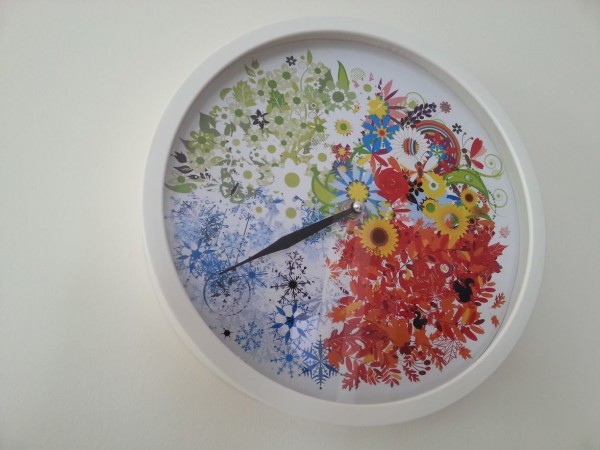
My wife Angela wanted a clock for her birthday where its one and only hand would go around once per year.
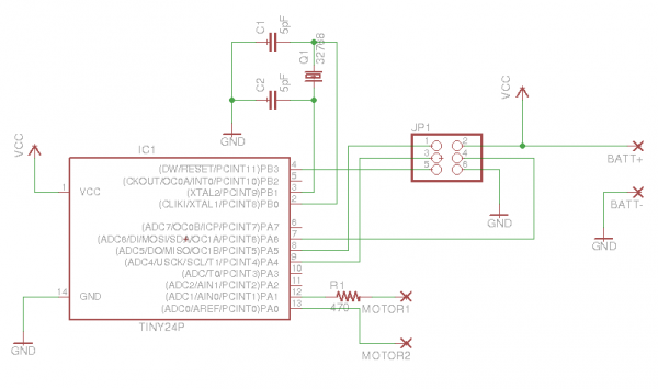
Sure, I can do that, I said. Angela chose a wall clock to modify, and chose artwork for the dial. I designed and built the circuit, and wrote the microcontroller code.
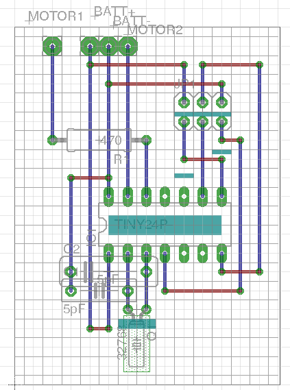
In-circuit programming made testing and debugging easy. I built the circuit on Veroboard.
Blue lines are copper tracks, red lines are jumpers. Cyan marks the track breaks, which I etched out with a dremel engraving bit.
I had to take the hands off to get the movement box open. The hands were made of metal barely thicker than foil, and it was necessary to use quite a bit of force to get them off the shaft. So I’m quite proud of myself for managing to save the minute hand and to get it back on to the shaft intact.
It was somewhat scary pulling the movement apart and putting it back together again. It was necessary to take all the tiny nylon gears out to get to the motor connections. When I put the case back on, one of the gear axles wasn’t quite lined up correctly, and it bent through almost 90°. I bent it back into shape by hand, and it somehow still worked afterwards.
The code is interrupt-driven. With a 32.768 kHz system clock in idle mode, the current draw was only 80µA, plus about 0.1µA average for driving the motor (3mA pulses with 0.004% duty cycle). So we can expect 3 years of battery life from a pair of AA alkalines.
/** * A driver for a standard battery-powered analogue clock, which will tick once * every 8766.15 seconds, so that the minute hand will complete a revolution once * per year. With the hour and second hands cut off, and appropriate artwork * attached to the dial, the minute hand will tell you what season it is. * * An ATtiny24/44/84 should be used, with a 32.768 kHz watch crystal attached * to XTAL1/XTAL2. PA0 and PA1 are used as a virtual H-bridge. * * According to Silicon Chip March 2008, a suitable pulse is 13mA for 100ms. * With 3V battery power, that suggests a current-limiting resistor in the * vicinity of 230 ohms. * * For my continuous sweep wall clock, the multimeter says: * * coil resistance = 560 ohm * * frequency at either port = 8 Hz * * duty cycle = 18.7% (implies 23.4ms pulse) * * VDC = 0.3V (divided by 18.7% implies full swing of 1.6V) * * So that implies a 560 ohm resistor for a supply of 3.2V * Note: dial diameter 237mm. * * Timer0 is used for pulse duration timing. Timer1, in combination with the * counter variable, is used as the real-time clock. * * LFUSE must be set to 0xe6 to enable the external crystal. */ #define F_CPU 32768 #include <util/delay.h> #include <avr/io.h> #include <avr/sleep.h> #include <avr/power.h> #include <avr/interrupt.h> #include <avr/wdt.h> static long counter = 0; static enum { PULSE_POSITIVE, PULSE_NEGATIVE } nextPulse; // 0.023 seconds with prescale 64 #define TICK_DURATION (short)(0.023 * F_CPU / 64) #ifdef TEST_MODE #define PERIOD_FACTOR_1 (unsigned int)(F_CPU / 16) #define PERIOD_FACTOR_2 1 #elif CLOCK_WAS_1HZ // Tick with period 50026*5742/32768 seconds // 50026 * 5742 / 32768 happens to be very close to the number of hours in // a year. So our minute hand will cover one revolution in one year, with a // residue here of only 8ms (although of course the quartz crystal is not // that stable, or even calibrated correctly) #define PERIOD_FACTOR_1 (unsigned int)(50026.0 * F_CPU / 32768) #define PERIOD_FACTOR_2 5742 #else /* 16 Hz */ // This is for continuous sweep movements that normally require 16 ticks per second // Tick with period 15845*1133/32768 seconds. // For testing, a square wave will appear on PA3 with frequency 1.034017 Hz. #define PERIOD_FACTOR_1 (unsigned int)(15845.0 * F_CPU / 32768) #define PERIOD_FACTOR_2 1133 #endif static inline void tick() { // Start the clock power_timer0_enable(); // Set up Timer0A to interrupt after the tick duration // Reset the counter TCNT0 = 0; // Enable output compare interrupt TIMSK0 |= _BV(OCIE0A); // Start the pulse if (nextPulse == PULSE_POSITIVE) { nextPulse = PULSE_NEGATIVE; PORTA |= _BV(PA0); } else { nextPulse = PULSE_POSITIVE; PORTA |= _BV(PA1); } } ISR(TIM0_COMPA_vect) { // End the pulse PORTA &= ~_BV(PA0); PORTA &= ~_BV(PA1); // Disable the interrupt and the timer module TIMSK0 &= _BV(OCIE0A); TCNT0 = 0; power_timer0_disable(); } ISR(TIM1_COMPA_vect) { // Toggle the test signal PORTA ^= _BV(PA3); if (++counter >= PERIOD_FACTOR_2) { // Cycle the stepper motor counter = 0; tick(); } } int main() { wdt_disable(); power_adc_disable(); power_usi_disable(); // Enable pullups for unconnected pins PORTA = ~_BV(PA0) & ~_BV(PA1) & ~_BV(PA3); PORTB = ~_BV(PB0) & ~_BV(PB1); // Set direction for outputs PA0, PA1 and PA3 DDRA = _BV(DDA0) | _BV(DDA1) | _BV(DDA3); // Set up Timer0 with prescale=64, but disable the clock initially TCCR0B = _BV(CS01) | _BV(CS00); OCR0A = TICK_DURATION; power_timer0_disable(); // Set Clear Timer on Compare mode TCCR1B |= _BV(WGM12); // Set clock source CLKIO no prescaler TCCR1B |= _BV(CS10); // Set the period OCR1A = PERIOD_FACTOR_1 - 1; // Enable interrupts sei(); TIMSK1 |= _BV(OCIE1A); // Interrupt loop with idle mode between interrupts set_sleep_mode(SLEEP_MODE_IDLE); while (1) { sleep_mode(); } } |


Interesting idea and execution. A tick every two hours and forty-four seconds, I’m guessing the most likely failure would come from the gear lubrication gumming up. Having reached retirement age a few years ago I can relate!
Does it still work?!
Yes, it’s still going, thanks!